Anyone have an guidance on a steering wheel adapter (possibly quick release) for a sparco 345 suede wheel?
Also what oil cooler setup are most of you guys running? Do you feel it necessary to run any other coolers as well (tranny, diff etc)?
Thanks in advance.
Full Version: Steering wheel adapter
QUOTE (pharmd @ Jul 19 2012, 11:39 PM) 
Anyone have an guidance on a steering wheel adapter (possibly quick release) for a sparco 345 suede wheel?
Also what oil cooler setup are most of you guys running? Do you feel it necessary to run any other coolers as well (tranny, diff etc)?
Thanks in advance.
Also what oil cooler setup are most of you guys running? Do you feel it necessary to run any other coolers as well (tranny, diff etc)?
Thanks in advance.
For HPDE events trans and rear end coolers are not really needed. Although I would put synthetic fluid in the rear, the trans could also use synthetic fluid.
A power steering cooler is needed, possibly with a re-valved pump from PSC($100). Try it with just the cooler first with Redline synthetic in the system. I use this cooler, cut a hole in the fan shroud under the passenger side fan and mounted it.
http://www.summitracing.com/parts/DER-13200/
The engine you are building might benefit from a cooler as it will be making some steam.
Improved racing makes an adapter that bolts above the oil filter, as far as the cooler itself look up "Long" or "stacked plate" oil coolers, use AN fittings and braided lines, get a 12-18 inch square cooler.
Personally I don't use an oil cooler, I use Royal Purple 10-40 and change it every 2 events. We run in the winter months only. Too damn hot down here to run in the summer.
QUOTE (FASTFATBOY @ Jul 19 2012, 07:57 PM)
QUOTE (pharmd @ Jul 19 2012, 11:39 PM)
Anyone have an guidance on a steering wheel adapter (possibly quick release) for a sparco 345 suede wheel?
Also what oil cooler setup are most of you guys running? Do you feel it necessary to run any other coolers as well (tranny, diff etc)?
Thanks in advance.
Also what oil cooler setup are most of you guys running? Do you feel it necessary to run any other coolers as well (tranny, diff etc)?
Thanks in advance.
For HPDE events trans and rear end coolers are not really needed. Although I would put synthetic fluid in the rear, the trans could also use synthetic fluid.
A power steering cooler is needed, possibly with a re-valved pump from PSC($100). Try it with just the cooler first with Redline synthetic in the system. I use this cooler, cut a hole in the fan shroud under the passenger side fan and mounted it.
http://www.summitracing.com/parts/DER-13200/
The engine you are building might benefit from a cooler as it will be making some steam.
Improved racing makes an adapter that bolts above the oil filter, as far as the cooler itself look up "Long" or "stacked plate" oil coolers, use AN fittings and braided lines, get a 12-18 inch square cooler.
Personally I don't use an oil cooler, I use Royal Purple 10-40 and change it every 2 events. We run in the winter months only. Too damn hot down here to run in the summer.
Im getting a turn 1 PS setup with billet pulley...they said most folks that run their setup don't need a PS cooler...so IDK. Does any one make a engine cooler "kit" that comes with all the hoses, fittings, cooler etc that you need to get it going?
QUOTE (pharmd @ Jul 19 2012, 04:39 PM)
Anyone have an guidance on a steering wheel adapter (possibly quick release) for a sparco 345 suede wheel?
Thanks in advance.
Thanks in advance.
I sell this splined, bolt on QD, and fab the 3bolt to 6bolt adapter:
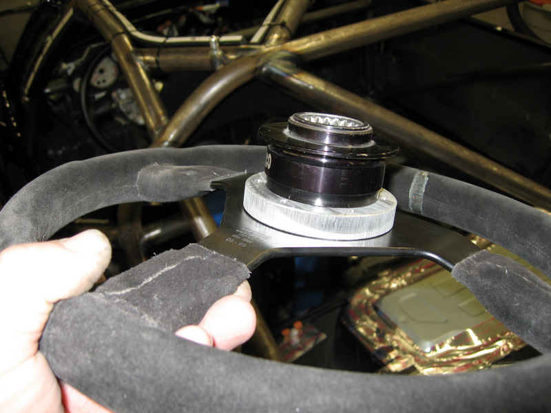
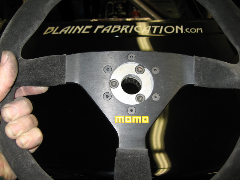
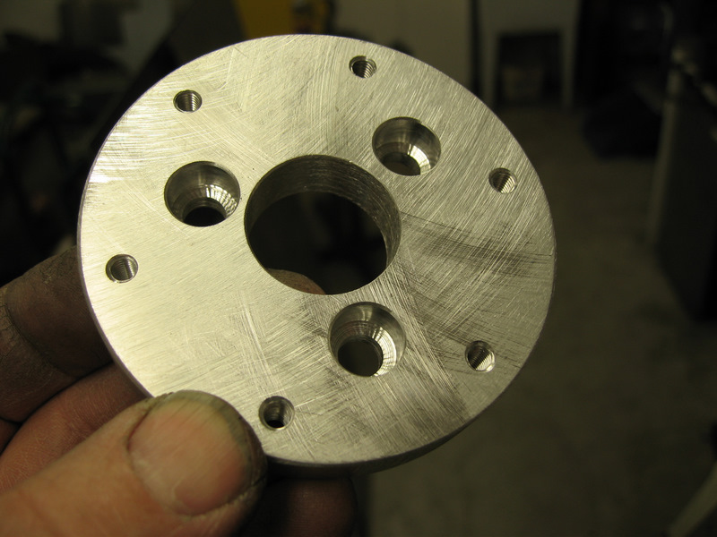
Except now I'm drilling more holes in the adapter and countersinking the 3 bolts flush, like this:
You'll lose the airbag. If you have a horn button with your wheel, I can make a spacer so it fits, you will need to wire an electrical tether for it.
QUOTE (Blainefab @ Jul 19 2012, 08:57 PM)
QUOTE (pharmd @ Jul 19 2012, 04:39 PM)
Anyone have an guidance on a steering wheel adapter (possibly quick release) for a sparco 345 suede wheel?
Thanks in advance.
Thanks in advance.
I sell this splined, bolt on QD, and fab the 3bolt to 6bolt adapter:
Except now I'm drilling more holes in the adapter and countersinking the 3 bolts flush, like this:
You'll lose the airbag. If you have a horn button with your wheel, I can make a spacer so it fits, you will need to wire an electrical tether for it.
Alan PM me a price for this with the spacer for horn. And do you have any other fire extinguisher mounts besides the roll bar mount?
If possible, would you be able to pm me the costs of your hub adapter as well? I have a momo Gotham steering wheel
QUOTE (The Batman @ Jul 20 2012, 05:16 AM)
I have a momo Gotham steering wheel.
Made of genuine bat suede, I take it??!
Alan, does that whole setup fit onto the stock, 4th gen f body steering shaft splines, or just your racing only steering column shafts??
QUOTE (pharmd @ Jul 19 2012, 08:22 PM)
Alan PM me a price for this with the spacer for horn. And do you have any other fire extinguisher mounts besides the roll bar mount?
PM sent on QD
I usually use rivnuts that have fingers that spread out on the backside, with a fender washer captivated by the fingers, and attach the bracket right onto the pan or tunnel, wherever there's enough flat space. The rollbar mount gives some other options if the space near the driver is full of other stuff.
I can make something custom at a reasonable price, too. Let me know what you are looking for.
QUOTE (dailydriver @ Jul 20 2012, 12:10 PM)
Alan, does that whole setup fit onto the stock, 4th gen f body steering shaft splines, or just your racing only steering column shafts??
This one is a bolt on to the OEM column on any 3rd or 4th gen Fbod, and C4 or C5 Ybod, and I'm sure there are others using the 36spline attachment.
There is some stuff that needs to come out to give space for the part that bolts to the shaft - the airbag clockspring, at least - it's retained by a circlip. The shroud can remain unmodified, but is a little tight to the QD for my fat fingers so I usually trim about 1/4" off of it.
How's my column coming along?
I know I still got another week of waiting, but I would love a teaser pic or three!!!
I know I still got another week of waiting, but I would love a teaser pic or three!!!
QUOTE (Blainefab @ Jul 20 2012, 04:35 PM)
QUOTE (dailydriver @ Jul 20 2012, 12:10 PM)
Alan, does that whole setup fit onto the stock, 4th gen f body steering shaft splines, or just your racing only steering column shafts??
This one is a bolt on to the OEM column on any 3rd or 4th gen Fbod, and C4 or C5 Ybod, and I'm sure there are others using the 36spline attachment.
There is some stuff that needs to come out to give space for the part that bolts to the shaft - the airbag clockspring, at least - it's retained by a circlip. The shroud can remain unmodified, but is a little tight to the QD for my fat fingers so I usually trim about 1/4" off of it.
Thanks, this part is in my future.
Most people dump ALL of the SRS pieces when they go to an aftermarket racing wheel anyway, at least I did.
Luckily, my state has gone to emissions only inspections, so they probably will not pick up on the illegal for street use quick release (they NEVER failed me yet for no driver's side airbag/sparco wheel, even when they DID a FULL inspection).
As far as I know, you must have safety items (this includes factory seat-belts, turn signals, rev lights, dash indicator lights, fog, driving and hi-beam lights) Fuel cap, fuel tank (I have a sure fire solution for this with my fuel cell) OBDII monitor history (which my car never came with) and IM120 or 240 emissions test depending on the county. They do not do full underhood inspections (phew) so as long as you have a good cat, you'll probably go through with flying colors
I'm not sure how close to the edge of failing an emissions ill be with my turbo V6, but I see no reason why the steer column would not pass. (unless you had an asshole doing the inspection on the car)
I'm not sure how close to the edge of failing an emissions ill be with my turbo V6, but I see no reason why the steer column would not pass. (unless you had an asshole doing the inspection on the car)
QUOTE (Driver_10 @ Jul 20 2012, 08:58 PM)
How's my column coming along?
I know I still got another week of waiting, but I would love a teaser pic or three!!!
I know I still got another week of waiting, but I would love a teaser pic or three!!!
Haven't received the parts from Woodward yet, I'll post up when I have it put together.
QUOTE (Driver_10 @ Jul 21 2012, 11:35 AM)
As far as I know, you must have safety items (this includes factory seat-belts, turn signals, rev lights, dash indicator lights, fog, driving and hi-beam lights) Fuel cap, fuel tank (I have a sure fire solution for this with my fuel cell) OBDII monitor history (which my car never came with) and IM120 or 240 emissions test depending on the county. They do not do full underhood inspections (phew) so as long as you have a good cat, you'll probably go through with flying colors
I'm not sure how close to the edge of failing an emissions ill be with my turbo V6, but I see no reason why the steer column would not pass. (unless you had an asshole doing the inspection on the car)
I'm not sure how close to the edge of failing an emissions ill be with my turbo V6, but I see no reason why the steer column would not pass. (unless you had an asshole doing the inspection on the car)
Inspections vary dramatically from state to state. I believe that the
airbag system is regulated by federal law, and there is some liability
involved in disabling them. It may not go well for someone who wrecks on
the street and their passenger is injured with the airbag disabled.
QUOTE (Blainefab @ Jul 21 2012, 08:53 PM)
QUOTE (Driver_10 @ Jul 21 2012, 11:35 AM)
As far as I know, you must have safety items (this includes factory seat-belts, turn signals, rev lights, dash indicator lights, fog, driving and hi-beam lights) Fuel cap, fuel tank (I have a sure fire solution for this with my fuel cell) OBDII monitor history (which my car never came with) and IM120 or 240 emissions test depending on the county. They do not do full underhood inspections (phew) so as long as you have a good cat, you'll probably go through with flying colors
I'm not sure how close to the edge of failing an emissions ill be with my turbo V6, but I see no reason why the steer column would not pass. (unless you had an asshole doing the inspection on the car)
I'm not sure how close to the edge of failing an emissions ill be with my turbo V6, but I see no reason why the steer column would not pass. (unless you had an asshole doing the inspection on the car)
Inspections vary dramatically from state to state. I believe that the
airbag system is regulated by federal law, and there is some liability
involved in disabling them. It may not go well for someone who wrecks on
the street and their passenger is injured with the airbag disabled.
Texas= not a problem.
The biggest thing that they look for is general failing safety equipment and lights. They will, however, fail an inspection if you don't have factory seat-belts in the car.
QUOTE (Blainefab @ Jul 21 2012, 04:53 PM)
QUOTE (Driver_10 @ Jul 21 2012, 11:35 AM)
As far as I know, you must have safety items (this includes factory seat-belts, turn signals, rev lights, dash indicator lights, fog, driving and hi-beam lights) Fuel cap, fuel tank (I have a sure fire solution for this with my fuel cell) OBDII monitor history (which my car never came with) and IM120 or 240 emissions test depending on the county. They do not do full underhood inspections (phew) so as long as you have a good cat, you'll probably go through with flying colors
I'm not sure how close to the edge of failing an emissions ill be with my turbo V6, but I see no reason why the steer column would not pass. (unless you had an asshole doing the inspection on the car)
I'm not sure how close to the edge of failing an emissions ill be with my turbo V6, but I see no reason why the steer column would not pass. (unless you had an asshole doing the inspection on the car)
Inspections vary dramatically from state to state. I believe that the
airbag system is regulated by federal law, and there is some liability
involved in disabling them. It may not go well for someone who wrecks on
the street and their passenger is injured with the airbag disabled.
Yes, but as long as you inform your insurance company (or they see it at their own point of insurance inspection) that you have disabled your driver's side airbag (and pay the subsequent additional premium, of course!), they WILL cover your injuries/medical expenses in an accident.

QUOTE (Blainefab @ Jul 21 2012, 08:12 PM)
QUOTE (Driver_10 @ Jul 20 2012, 08:58 PM)
How's my column coming along?
I know I still got another week of waiting, but I would love a teaser pic or three!!!
I know I still got another week of waiting, but I would love a teaser pic or three!!!
Haven't received the parts from Woodward yet, I'll post up when I have it put together.
Parts in yet? Pics?
QUOTE (Driver_10 @ Jul 31 2012, 07:38 AM)
QUOTE (Blainefab @ Jul 21 2012, 08:12 PM)
QUOTE (Driver_10 @ Jul 20 2012, 08:58 PM)
How's my column coming along?
I know I still got another week of waiting, but I would love a teaser pic or three!!!
I know I still got another week of waiting, but I would love a teaser pic or three!!!
Haven't received the parts from Woodward yet, I'll post up when I have it put together.
Parts in yet? Pics?
Woodward says they will ship this week, they've been unusually busy.
Hey, Alan... different subject.
Do you have the part numbers, or at least a full parts description of all the modules you used in your c5 ABS swap? Im not very familiar with the layout of the C5 modules or networks. As far as I know, its just the hyd actuator module, and the ECM (or ABS controller or whatever)
Also, Ill remind you, I don't have an LS engine in this car. RPM or TPS sensor input would be perfectly futile.
So in summary, "plug in the sensors, install the ECM, install the ABS hyd box and give it power" and this will give me fuctioning, 4-channel ABS?
C5 ECM + wheel speed sensors + ABS actuator module + batt power = complete ABS system?
QUOTE (Driver_10 @ Jul 31 2012, 06:08 PM)
Hey, Alan... different subject.
Do you have the part numbers, or at least a full parts description of all the modules you used in your c5 ABS swap? Im not very familiar with the layout of the C5 modules or networks. As far as I know, its just the hyd actuator module, and the ECM (or ABS controller or whatever)
Also, Ill remind you, I don't have an LS engine in this car. RPM or TPS sensor input would be perfectly futile.
So in summary, "plug in the sensors, install the ECM, install the ABS hyd box and give it power" and this will give me fuctioning, 4-channel ABS?
C5 ECM + wheel speed sensors + ABS actuator module + batt power = complete ABS system?
Do you have the part numbers, or at least a full parts description of all the modules you used in your c5 ABS swap? Im not very familiar with the layout of the C5 modules or networks. As far as I know, its just the hyd actuator module, and the ECM (or ABS controller or whatever)
Also, Ill remind you, I don't have an LS engine in this car. RPM or TPS sensor input would be perfectly futile.
So in summary, "plug in the sensors, install the ECM, install the ABS hyd box and give it power" and this will give me fuctioning, 4-channel ABS?
C5 ECM + wheel speed sensors + ABS actuator module + batt power = complete ABS system?
I started with a C5 EBCM and a wiring harness, Ken got them off of Ebay. I'll get you the part numbers. I needed the wiring harness only for the connector that plugs into the EBCM - it is a unique, multi pin connector.
The C5 ABS combines the hydraulics and electronics in the EBCM, so just the one module to mount. I replicated the C5 mounts, with 3 studs that engage rubber donuts in the EBCM, and located it near where the OEM Fbody ABS hydraulic module is located.
The ports on the C5 EBCM are labeled with function
For plumbing, I installed new LS1 Fbody front hardlines, they have a flex section at the ABS end, and the bubble flare fittings are compatible with the C5 EBCM, so just had to bend the hardlines up a bit, and plug them in.
I fabbed up new rear hardlines from the EBCM back to the axle, and used Global West chassis to axle flex lines. I fabbed new axle hard lines.
I put a new LS1 MC and booster on the car, and using a new set of LS MC hardlines as a starting point since the MC fittings are oddball, fabbed new hardlines from the MC to the EBCM. The rear line goes thru a Wilwood bias adjuster.
Electrical:
Red +12V thru a 25A fuse to the alternator
Blk, Blk/Wh Ground to chassis
Brn ign to switched side of ignition circuit - I put a dash switch with pilot light on this connection so the driver can turn the ABS system on/off on the fly.
Lt Blu stop to switched side of stop light circuit
a twisted pair from each wheel sensor:
left rear: Red/Blk
right rear: Wh/Brn
right front: Tan/Grn
left front: Yel/Blu
I salvaged the front hub harnesses, axle wiring harness and the rear bulkhead connector from a 4channel Fbody chassis, made up the rest of the rear twisted pairs.
That's it - no connection to a PCM, so this could go on anything, carb or EFI or whatever
There are no ABS ERR or ABS ACTIVE indicators, nor any diagnostic port - those would need to be wired thru a compatible PCM.
Bleeding - connect everything, bleed, leak check, drive it a bit in the paddock, carefully activating ABS, use some water or gravel if necessary, then bleed again. Rinse and repeat. It is important to get the system bled - air in the ABS system will try to kill you - ie pedal stuck to the floor with both fronts locked up. Do not drive it on track or on the street until you are satisfied that the system is fully bled of air.
Wow... So its just one single module + sensors/w associated wiring. How ridiculously simple.
I was originally intending on using the controller and module from a C4. It must be divine intervention that you happened to do this first. I thought I was going to find myself trailblazing my own R&D like so many times in the past.
And thanks in advance for any part numbers you come across!
I was originally intending on using the controller and module from a C4. It must be divine intervention that you happened to do this first. I thought I was going to find myself trailblazing my own R&D like so many times in the past.
And thanks in advance for any part numbers you come across!
QUOTE (Driver_10 @ Aug 1 2012, 04:20 AM)
And thanks in advance for any part numbers you come across!
Here's the EBCM that I installed in Kens car:

And here are the tags on the wiring harness that I got the connector from:

Looks like a build date of 4/3/2003 on the harness:

And for more options, here are the EBCM numbers from the 2001 C5 Z06 boxcar I have in the shop:
It has zero miles on it. I can sell it, but the bad news is that I'd need $60K for it. The good news is that you'd also get one bitching race car for that $60K: http://jeffstevens.org/C5R-kit.htm

QUOTE (Blainefab @ Aug 2 2012, 09:06 AM)
And for more options, here are the EBCM numbers from the 2001 C5 Z06 boxcar I have in the shop:
It has zero miles on it. I can sell it, but the bad news is that I'd need $60K for it. The good news is that you'd also get one bitching race car for that $60K:
It has zero miles on it. I can sell it, but the bad news is that I'd need $60K for it. The good news is that you'd also get one bitching race car for that $60K:
60k huh? Really I would, but I already sold my kidney to get my project finished. I need the other one to live.
BTW... did Woodard ship out the goodies already?
QUOTE (Driver_10 @ Aug 4 2012, 06:38 AM)
BTW... did Woodard ship out the goodies already?
Woodward says the column will ship out today
QUOTE (Blainefab @ Aug 8 2012, 09:21 PM)
Woodward says the column will ship out today
Good stuff! (took em' long enough)
Thnx for the update, BTW.
Any steer-column pics yet?
QUOTE (Driver_10 @ Aug 14 2012, 09:43 AM)
Any steer-column pics yet?
Got it, pics tonite

Goodies from Woodward, fab time for me:

QUOTE (Blainefab @ Aug 15 2012, 10:05 AM)
Goodies from Woodward, fab time for me:
Good stuff. Cant wait to see it!
QUOTE (Blainefab @ Aug 8 2012, 05:21 PM)
QUOTE (Driver_10 @ Aug 4 2012, 06:38 AM)
BTW... did Woodard ship out the goodies already?
Woodward says the column will ship out today
Would this be my adapter also?
QUOTE (pharmd @ Aug 21 2012, 01:15 AM)
Would this be my adapter also?
Speaking of which... Any closer to finishing?
QUOTE (Driver_10 @ Aug 21 2012, 03:25 PM)
QUOTE (pharmd @ Aug 21 2012, 01:15 AM)
Would this be my adapter also?
Speaking of which... Any closer to finishing?
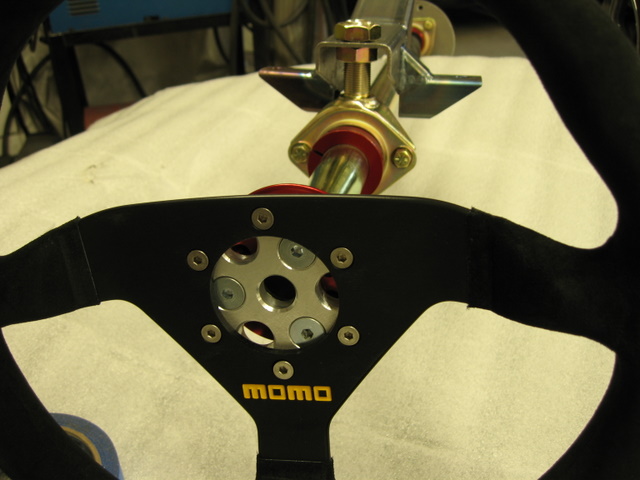
Last nights work:


QUOTE (Blainefab @ Aug 22 2012, 08:04 PM)
QUOTE (Driver_10 @ Aug 21 2012, 03:25 PM)
QUOTE (pharmd @ Aug 21 2012, 01:15 AM)
Would this be my adapter also?
Speaking of which... Any closer to finishing?
Last nights work:
Wow... freakishly high standards as usual. Outstanding work.
QUOTE (Blainefab @ Jul 20 2012, 12:57 AM)
I sell this splined, bolt on QD, and fab the 3bolt to 6bolt adapter:
Except now I'm drilling more holes in the adapter and countersinking the 3 bolts flush, like this:
You'll lose the airbag. If you have a horn button with your wheel, I can make a spacer so it fits, you will need to wire an electrical tether for it.
Except now I'm drilling more holes in the adapter and countersinking the 3 bolts flush, like this:
You'll lose the airbag. If you have a horn button with your wheel, I can make a spacer so it fits, you will need to wire an electrical tether for it.
What quick disconnect do you use when using a stock Column in a 4th gen? I contacted you on a price for the quick disconnect and adapter a while back, but I was curious as to what is all there for hardware. Thank you.
QUOTE (The Batman @ Nov 10 2012, 09:29 PM)
QUOTE (Blainefab @ Jul 20 2012, 12:57 AM)
I sell this splined, bolt on QD, and fab the 3bolt to 6bolt adapter:
Except now I'm drilling more holes in the adapter and countersinking the 3 bolts flush, like this:
You'll lose the airbag. If you have a horn button with your wheel, I can make a spacer so it fits, you will need to wire an electrical tether for it.
Except now I'm drilling more holes in the adapter and countersinking the 3 bolts flush, like this:
You'll lose the airbag. If you have a horn button with your wheel, I can make a spacer so it fits, you will need to wire an electrical tether for it.
What quick disconnect do you use when using a stock Column in a 4th gen? I contacted you on a price for the quick disconnect and adapter a while back, but I was curious as to what is all there for hardware. Thank you.
This is the QD I sell for the OEM column: The splined part slips onto the column and is retained by a nut, much like the OEM wheel. Then the black aluminum hub slips over the splined part and locks in place with the spring loaded ring. It has a standard 3 bolt pattern that accepts a circle track style wheel directly. In order to use a 6 bolt wheel (Momo/Sparco/Personal/etc) I also offer a 3bolt to 6bolt adapter - the silver aluminum piece that is pictured installed on the hub.
The QD hub includes the splined part, a nut, the hub and 3 screws. The 3-6bolt adapter includes 3 flathead screws and 6 stainless flathead screws for attaching the wheel.
I am also a Momo dealer, the model 78 in 330mm or 350mm in black suede is the most popular model for a race car. For a street car, driven with bare hands, I recommend a smooth leather wheel, the Momo Monte Carlo is the pick there.

Alan.. I pm'ed you, but I like the looks of that adapter.
James
James
QUOTE (Blainefab @ Nov 12 2012, 02:59 AM)
For a street car, driven with bare hands, I recommend a smooth leather wheel, the Momo Monte Carlo is the pick there.
Some of us just love the feel/control of suede so much that we use those wheels even for the street.
YES, it will get matted down, and end up smooth anyway if you drive it bare handed.
I try to avoid this by using suede gloves, even on the street, and even in the summer, much to the ridicule and consternation/embarrassment of my kids. I also take a brass/stainless brush to it at least once a week, which seems to help a lot.
This is a "lo-fi" version of our main content. To view the full version with more information, formatting and images, please click here.